Bring geometry, forces and data together. Seven engineering products cover joint design and verification, testing and measurement, assembly and in-service monitoring.
Start with the applicable standards, parameters and assumptions. Use them to design and verify the joint. As external load changes, bolt tension and residual clamping force change as well.
Atlas · Dimension basisGB/T 196—2025M16 × 2 d₂ 14.701 mm D₁ 13.835 mm
Preload connection force - deformation coordinationbolt tension clamp release
FS − FK = FA
The joint interface remains in compression
This coaxial linear spring example normalizes preload and assembled bolt elongation to 1, with a clamped member-to-bolt stiffness ratio of 3. It is separate from the Axiom calculation case. D₁ denotes the basic minor diameter of the internal thread.
Inspect a single thread. Then return to the full joint.
Local thread response depends on accurate profiles and meshes. Load transfer through complex structures also depends on contact, boundary conditions and interactions between joints.
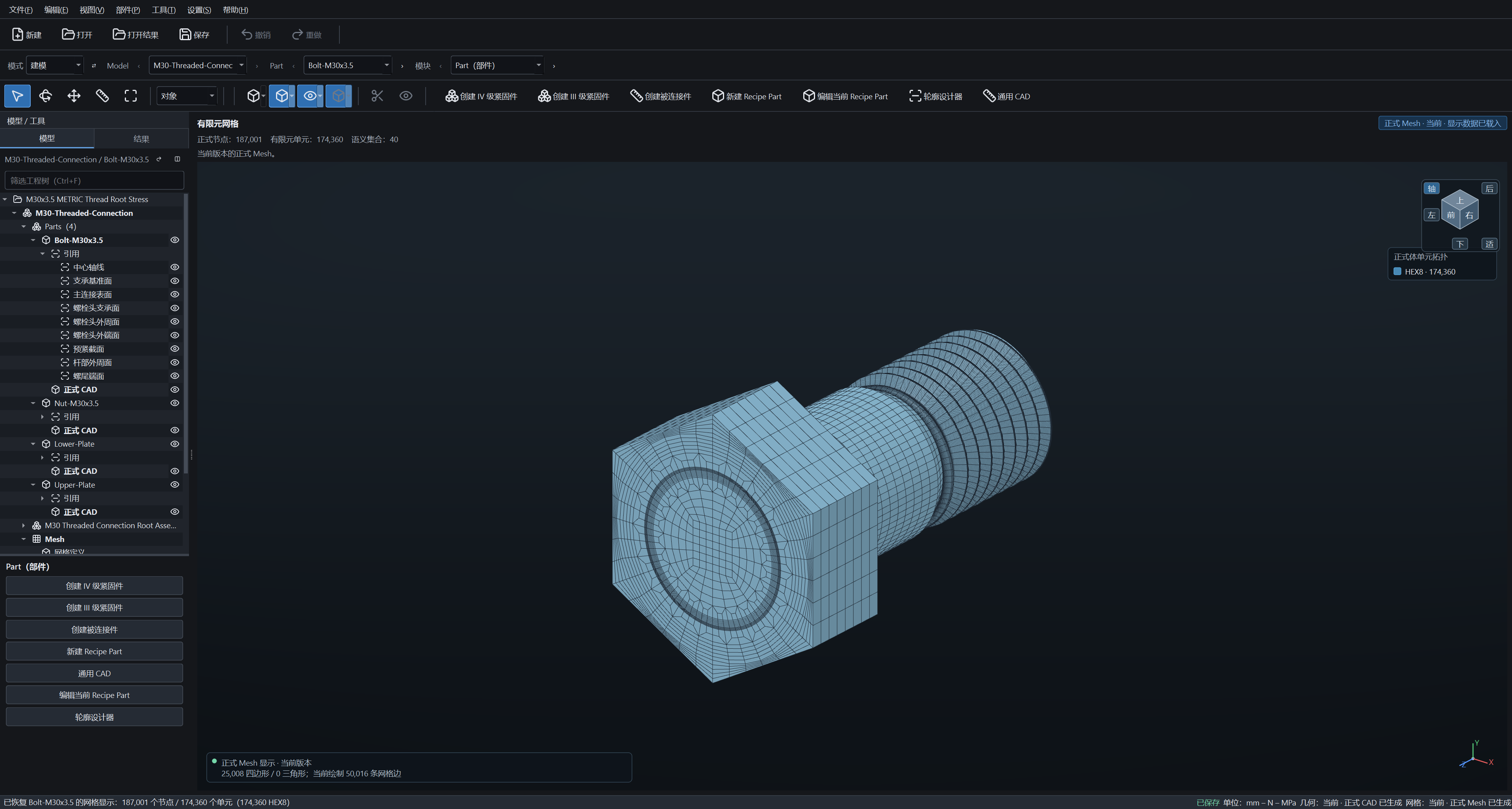
M30 × 3.5 · 6 threads of engagement
Inspect the bolt and nut using actual HEX8 element surfaces and mesh sections. Local analysis starts with the thread profile, engagement length and mesh settings.
Switch between two independent cases, the Forge M30 thread model and the Nexus end-frame structure. Each case was calculated separately.
TD SenseDesign verification / assembly test / measurement study
Complement your calculations with measurements.
Put data collection, calibration, and analysis into the same project. When processing signals, retain its original appearance and also retain the conditions of each step of processing.
Example signal / normalized amplitude128 Hz · 2 s
Window Widened, Details May Be Diminished
Synthetic signal and moving average demonstration. Measurement accuracy needs to be evaluated in combination with instruments, calibration and test conditions.
From target preload to process records, to the tightening sequence of the connection group. After assembly, retain the tools, measurement, and verification background.
current position 01 / 12process progress 0%
Single Point Tightening Process / Normalized Illustrationtorque axial force
12-point tightening sequence and curve display the planned assembly function, using illustrative data. The current software supports torque and axial force measurement, calibration, and playback recording.
Where and when do the changes occur? Only by combining axial force, temperature, data quality, and maintenance events can the next verification direction be determined.
—
Axial Force / kN · Synthetic ScenarioP03 / original bolt
Trend change: first verify temperature and measurement conditions, then schedule recheck.
Service scenarios use synthetic data to demonstrate planned monitoring functions. When data is missing, it is impossible to determine the joint status; after replacing bolts, a new baseline must be established, tracing both the previous and current records separately.
Bring verified experience Reference for the Next Design
Seven software packages work together in the field of joint engineering. Each case is annotated with data sources and applicable conditions; cross-software data collaboration and experience feedback are still in planning.
Seven products with distinct roles in one workflow.
Select any one and see the problem it solves. It can also be done according to the current task, finding the next required tool.
design and verificationassembly and maintenance
Common knowledge and data foundation
Selected Product related processes Select tools according to engineering tasks; each software can be used independently; the connection indicates collaboration direction
TD Axiom
design and verification
From parameters to judgment, make the verification process verifiable.
Organize geometry, material, load, and calculation steps according to VDI 2230, connecting design inputs, verification results, and reports.
Related software and collaboration
Atlas provides basis; local thread details can be directed to Forge, complex structures and connection groups can be directed to Nexus.
Various professional software work around the project, operation, and AI assistant. Atlas provides knowledge basis, results return to the engineer for verification.
TD Axiom
Collaboration process demonstration
Is the verification basis for this joint complete?
01
Understanding Context
Current connection, material, load, and verification step
02
provide a checkable plan
Read current parameters, list sources and missing items, then propose verification steps.
03
Confirm and execute the action
The write and calculation actions of the project need to be clearly authorized and retain execution records
04
Return to results that can be re-verified
Generate a parameter check list and calculation step explanation; whether it passes still depends on the complete verification results of the project.
1 / 4
Predefined process demonstration, not connected to AI services or actual projects. Achieved functions can be viewed in various product stations.
Show the evidence behind your engineering decisions.
View the model, parameters, and results in the workspace. Software screenshots and conceptual interfaces are all labeled with type and data source.
TD AxiomB1 Geometry Workspace
click to zoom in
Verification starts with the model and its inputs.
Actual software interface · B1 case
B1 example engineering geometry workspace, using an equivalent thread model. The product station can view material, load, verification results, and draft calculation book.